
A rooftop solar array sized only against annual electricity use may look adequate on paper yet contribute little during a building’s evening peak. That matters if the owner expects to reduce peak demand charges or keep essential services running during an outage. Architects, engineers and operators need to agree early on which loads matter, when they occur and where generation equipment can safely go.
Buildings can accommodate rooftop or facade-mounted photovoltaics, solar thermal collectors, heat pumps and, on suitable sites, small wind turbines or connections to district renewable energy. Each option has consequences beyond the energy model. Roof form, structural loads, plant space, maintenance access and appearance may all change. The aim is to fit a dependable system to the building’s use and site, not to fill every available surface with equipment.
Start with demand, not equipment
First, separate energy demand from supply. Insulation, glazing, shading, airtightness and efficient systems reduce what a building needs; renewable systems provide or move energy to meet what remains. Lower loads may allow a smaller solar or heat-pump installation, although demand-reduction measures have costs and constraints of their own. In an occupied building, for instance, envelope upgrades may be difficult without disrupting users or changing a protected facade.
The team should model electricity, heating, cooling and domestic hot water demand by month at a minimum, and by hour where possible. Timing matters: solar output seldom matches building use exactly. A school may export electricity on summer days when few people are present; a hospital still has substantial loads overnight. Record occupancy schedules, equipment loads and weather assumptions so that later design changes do not quietly undermine the estimate.
- Define the objective: reduce annual energy purchases, lower peak demand, cut operational emissions or maintain specified services during an outage.
- Identify the loads: assess electricity, space heating, cooling and hot water separately rather than treating them as interchangeable.
- Check the site: measure usable roof or ground area, shading, structural capacity, utility connections and restrictions on visible equipment.
- Test operation: estimate generation by season and time of day, then account for storage, export rules and maintenance access.
These checks also prevent a basic comparison error: treating rated capacity as annual output. A photovoltaic array’s nameplate capacity is measured under specified test conditions. Its production on site depends on orientation, shading, temperature, location and equipment losses.
Where renewable systems fit in the building
Solar photovoltaics: generation with architectural consequences
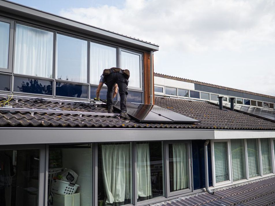
Photovoltaic panels are often the most visible part of a renewable installation. A simple, unobstructed roof is usually easier to lay out and maintain than one crowded with skylights, vents and changes in level. The layout needs to allow for setbacks, access routes, fire-safety requirements and spacing where rows might shade one another. Panels add dead load and can be subject to wind-uplift forces, so structural capacity must be checked on new buildings and retrofits alike.
South-facing panels can be productive in the Northern Hemisphere, but orientation should reflect the site and electricity tariff. An east–west layout may spread output across more of the working day, even if annual generation per panel differs. In dense areas, neighboring buildings—and future development—can restrict sunlight. Shadow studies should look beyond the proposed building itself.
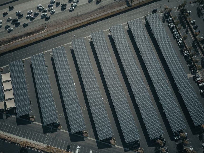
Panels can also cover parking areas or be integrated into facades. A canopy may provide shade, while facade panels may replace conventional cladding, but neither has the same costs or construction details as a standard roof-mounted array. Facade systems need careful detailing for weatherproofing, replacement access, fire performance and electrical penetrations through the envelope. Building-integrated photovoltaics must be specified as building elements as well as electrical equipment.
Heat pumps and the source of heat
Heat pumps transfer heat rather than produce it through combustion. Air-source units exchange heat with outdoor air; ground- and water-source systems use the ground or a suitable water body. Electrical demand, heating output and efficiency all vary with operating conditions. An outdoor air-source unit needs adequate airflow, a position that limits noise impacts and room for servicing. Indoors, plant rooms and distribution routes must fit the selected equipment.
Heat pumps generally work best with systems that can maintain comfort at lower water temperatures, such as appropriately sized radiators or radiant systems. In a retrofit, undersized emitters may force higher operating temperatures and reduce efficiency. Cooling needs, hot-water temperatures and any simultaneous demand for heating and cooling also affect selection. Ground-source systems require additional site investigation and installation work; they are not an automatic upgrade over air-source equipment.
Solar thermal, wind and shared systems
Solar thermal collectors heat a fluid that can supply domestic hot water with suitable storage and controls. They may suit buildings with steady hot-water demand, but the team must assess roof area, summer surplus, freeze protection and maintenance. If photovoltaics paired with electric water heating are another option, compare the complete systems against the building’s demand profile—not panel efficiencies in isolation.
Small wind turbines depend heavily on the site. Turbulence around buildings can sharply reduce output and cause vibration or noise, making a resource assessment and local permission checks essential. In some urban projects, a district energy network or renewable electricity procurement may be more practical than installing every source on-site. An off-site electricity contract, however, does not provide backup power when the grid fails.
Designing for timing, storage and resilience
Annual energy balance tells only part of the story. A building can generate as much electricity over a year as it consumes and still draw from the grid every night and on low-generation days. The value of on-site generation depends in part on when the building uses power and what it receives for exports. Tariffs and interconnection rules vary, so financial assumptions need to match the jurisdiction and utility agreement.
A battery can shift solar electricity into later hours or support selected loads. It also takes up space, needs thermal management, adds cost and will eventually need replacement. Size storage against a defined load and duration: keeping emergency lighting and communications running for several hours is very different from operating all heating and cooling through a long outage. A solar array on its own commonly shuts down during a grid failure unless approved equipment allows it to operate independently.
If backup power is a goal, the electrical engineer should identify critical circuits, starting currents and required operating time. The architect must allow space and access for batteries and related equipment, including any separation required by applicable codes. A clear transfer and control strategy should tell maintenance staff what stays powered during an outage.
What changes in planning and construction
Renewable systems are easier to coordinate before roof geometry and plant space are fixed. On a new building, the team can keep a contiguous roof area available for solar, plan cable routes and place inverters and switchgear near suitable electrical rooms. On a retrofit, the roof may need repair or replacement first. Having to remove panels for an early roof replacement can damage the financial case.
Permitting depends on location and system type. Reviews may address appearance, structural adequacy, fire access, electrical safety, equipment noise and grid connection. Heritage rules or roof setbacks can limit panel placement; outdoor heat-pump units may face acoustic limits near homes or patient rooms. Utility interconnection approval can take longer than installation, so it needs a place on the schedule from the outset.
Coordination drawings should show roof penetrations, waterproofing, lifting and replacement routes, access clearances and where one trade’s responsibility ends and another’s begins—not just equipment footprints. The roofing contractor, solar installer and designer, for example, need to agree how supports will be fixed without compromising drainage or the roof warranty. Resolving that on drawings is far less disruptive than correcting it after occupancy.
Assessing costs without relying on a headline payback
A sound comparison covers installation, grid-connection work, operation, maintenance and replacement over an agreed study period. Electricity price forecasts, incentives and export payments can materially change the outcome; show those assumptions rather than hiding them in one payback figure. Compare the proposal with reasonable alternatives, too: reducing demand, installing a smaller array, choosing another heat source or buying energy from the grid.
Use the same energy prices, equipment lives, maintenance allowances and discount rate across financial options. Account separately for emissions reduction or outage protection if the owner values them; neither benefit necessarily appears on a utility bill. The method used to assess wider building costs is explored in How to Assess the Economics of a Building Design.
Ask for a range of outcomes, not just a best-case forecast. Test lower solar production, higher installation costs and changes to export compensation. For heat pumps, use plausible seasonal efficiency to test operating costs rather than a single peak laboratory figure. A proposal that works only under unusually favorable assumptions carries risks the owner should see before procurement.
Performance after handover
Commissioning should confirm that the installed system works as designed and that its controls respond to actual building use. Metering needs to distinguish renewable generation from total consumption and, where relevant, record battery charging and discharge. Otherwise, a lower electricity bill might reflect reduced occupancy rather than good system performance.
Give the operations team as-built drawings, warranties, shutdown instructions and a maintenance schedule. Cleaning and inspection needs depend on the installation and local conditions; safe, practical access should be designed in rather than assumed unnecessary. After the building has been through both a heating and a cooling season, compare measured demand and generation with the design model and investigate material differences.
For a rooftop photovoltaic system, that review can start with a specific check: compare the inverter’s recorded output with the dedicated generation meter over the same period. If the readings differ beyond expected metering tolerances, investigate the discrepancy before relying on either figure to judge performance.