
Remove a ground-floor wall to open up a lobby, and the building may respond differently to an earthquake. If the upper floors remain stiff while the ground floor becomes flexible, deformation can concentrate in the columns below. A stronger beam or an advanced damper cannot reliably make up for that break in continuity without analysis and detailing of the entire load path. The first question for owners and design teams is how earthquake forces will pass through the floors and structure into the ground—not which seismic technology is newest.
Earthquake-resistant design serves two different aims: protecting life during severe shaking and limiting damage in more frequent events. Building codes generally set minimum requirements focused primarily on safety. They do not promise a building that is undamaged or ready for immediate use. A hospital, emergency facility or business facing costly downtime may need a higher performance target. That choice shapes the structural system, architectural layout, equipment anchorage, budget and post-event inspection plan.
Establish the hazard and the performance target
A regional hazard map is only part of the site assessment. Local soil can amplify shaking; liquefaction, lateral spreading, slope movement and fault displacement pose problems beyond vibration. A geotechnical investigation should guide foundation selection and show whether ground improvement or a different site arrangement is needed. Even a carefully designed superstructure cannot prevent settlement if the ground beneath it loses strength.
Before choosing a structural system, the team should agree on what level of damage is acceptable. A practical brief might distinguish:
- Life safety: occupants can escape, even if repairs are extensive and the building cannot be used afterward.
- Repairability: structural and architectural damage falls within a planned repair strategy for a defined level of shaking.
- Continuity: essential spaces and systems can function after inspection and any necessary repairs.
These are goals, not guarantees. Engineers must turn them into criteria suited to the applicable code, site hazard and occupancy. Owners also need to identify what is critical. In a hospital, clinical equipment and backup utilities may matter as much as the structural frame.
Make the building form work with the structure
A regular, continuous structural layout is usually easier to predict and detail than one with abrupt setbacks, discontinuous walls or sharp changes in floor stiffness. If the center of mass is far from the main lateral-resisting elements, shaking can twist the building as well as push it sideways. Shear walls around a core may be efficient, but their position still needs to be assessed against the floor plan and perimeter.
The load path begins at the floor diaphragm, which collects horizontal forces. Collectors and connections pass those forces to frames or walls, and foundations transfer them to suitable ground. Stairs, atria and service openings can interrupt that path. Structural coordination needs to happen early, before a large atrium or transfer level becomes an expensive constraint.
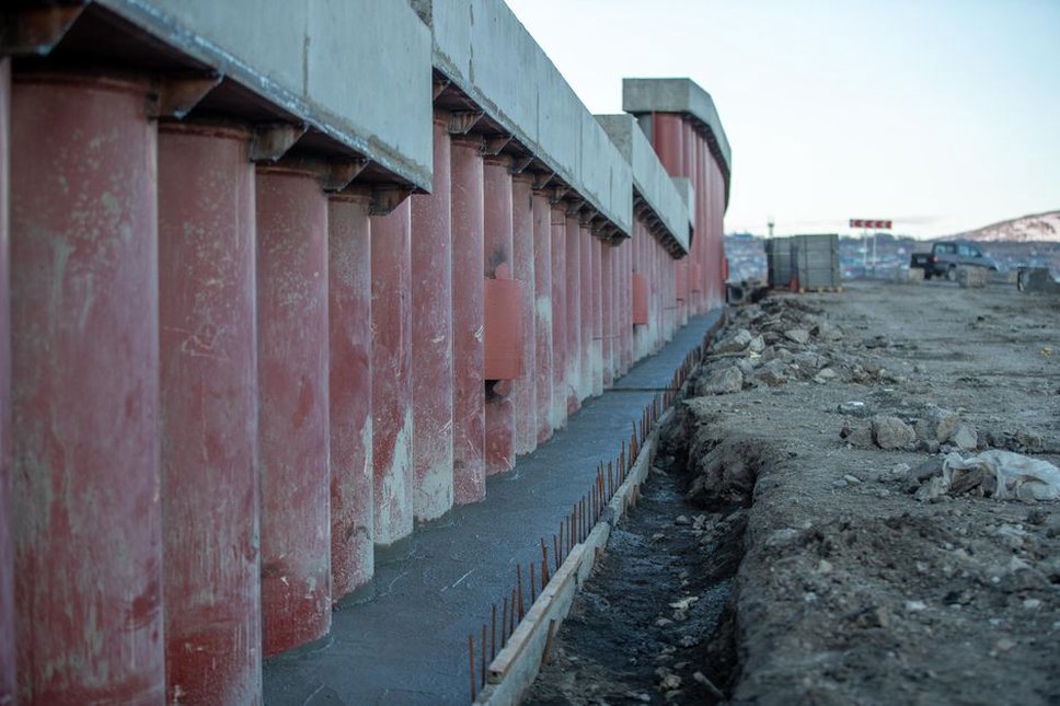
Choose a lateral system for the building's use
Shear walls, braced frames and moment frames
Reinforced-concrete shear walls provide substantial lateral stiffness and can fit around lift and stair cores. Steel braced frames are also relatively stiff, though their diagonals may conflict with doors, glazing or flexible tenancy layouts. Moment frames resist lateral forces through rigid beam-column connections. They leave more open bays but often allow greater drift. That flexibility is not automatically a problem: the design must account for both demands on structural members and the movement that partitions, façades and services can tolerate.
Engineers may combine systems where codes permit, but the load sharing needs careful analysis. A stiff wall can attract much of the force while nearby frames move with it; design assumptions must reflect actual stiffness, connections and detailing. Judging a system only by the apparent price of its frame also misses foundation costs, fire protection, façade movement joints and limits on floor planning.
Ductility depends on details
A structure does not have to remain perfectly elastic to protect occupants. Many seismic systems are designed to deform in a controlled way, dissipating energy in intended locations while avoiding brittle failure. That depends on reinforcement confinement, connection design, capacity protection and construction quality. Requirements vary by material, system and jurisdiction.
In a reinforced-concrete frame, reinforcement layout and joint detailing are not minor drafting matters. Congested joints can be difficult to place and consolidate correctly. In steel systems, fabrication tolerances and inspection of critical connections matter just as much. A detail is useful only if it can be built and checked on site.
When advanced systems change the outcome
Base isolation
Base isolation places a flexible, controlled interface between the building and its foundation. It lengthens the structure's effective period and, in suitable conditions, can reduce the shaking transmitted to floors. That may help when protecting equipment and limiting disruption are priorities. But isolation needs room for the building to move, compatible stairs and utility connections, accessible bearings, and checks against the full range of expected ground motions. Site conditions, height and building configuration also affect whether it is suitable.
Energy-dissipating devices
Dampers absorb some of the energy associated with structural motion. They can be integrated with braces in a new building or considered in a retrofit. Their benefit depends on placement, the deformation each device experiences, and whether the surrounding structure and foundations can carry the resulting forces. Maintenance access, replacement procedures and post-event inspection requirements should be settled before the design is finalized.

Self-centering systems and replaceable components
Some newer systems seek to reduce residual drift—the permanent lean that can make a standing building difficult to repair. Examples include rocking walls, post-tensioned connections and replaceable energy-dissipating components. They can provide a planned route to repair, but performance depends on the whole assembly, including floor connections and nearby nonstructural elements. Check the availability of specialist parts, approval requirements and contractor familiarity before making such a system central to the project.
Protect what the frame does not protect
A structure may perform well while the building loses its function: ceilings fall, façades crack, water lines rupture or equipment shifts. Nonstructural components need appropriate restraint and enough room to accommodate story drift or isolation movement. Heavy generators, tanks and medical equipment need anchorage designed for the expected forces and the supporting substrate, rather than whichever fastening points are convenient.
Interfaces deserve particular attention. A façade must accommodate relative movement without falling into an exit route. Sprinkler and utility connections may need flexible sections at movement joints. A partition built tight against a drifting frame can be damaged or interfere with the intended structural behavior. If the building is expected to operate after an earthquake, the owner should identify critical rooms and service routes, then trace the dependencies needed to keep them usable.
Assess cost through construction and recovery
The lowest initial structural cost may not mean the lowest cost over the building's life. Compare foundations, structural quantities, specialist devices, installation and inspection, expected repairs, likely downtime and operational consequences. Any estimate has uncertainty: no one can predict when or how intensely an earthquake will affect a particular building. Scenario-based comparisons are more honest than a single promised payback figure.
Buildability belongs in the calculation. Dense reinforcement may take more labor and inspection time than drawings suggest. Access for replacing isolation devices can shape basement planning. A system dependent on a limited supply chain may face long procurement times, affecting both construction and recovery. Recording these assumptions lets an owner compare a conventional code-compliant scheme with a higher-performance option on consistent terms.
Keep seismic intent intact during delivery
Approval of the design does not protect it against later changes. A proposed penetration through a shear wall, a relocated brace, an unreviewed façade fixing or a tenant fit-out can alter the intended load path or movement capacity. The design team needs a process for reviewing such changes and clear responsibility for revised calculations and drawings.
At handover, the owner should receive records of critical structural details, applicable device specifications, inspection results and limits on future alterations. Maintenance plans for dampers or isolators should identify access points and inspection triggers after significant shaking. Then walk each seismic movement joint in the finished building: a pipe, conduit or finish that bridges the gap may prevent it from working as designed.